


 619/ Anchor Handling and Towing Operations Procedure / 992

A
nc
h
or
H
andlin
g
and To
w
in
g
O
p
erations
P
rocedure
BOS-
P
RD-2
6
.900
6
14
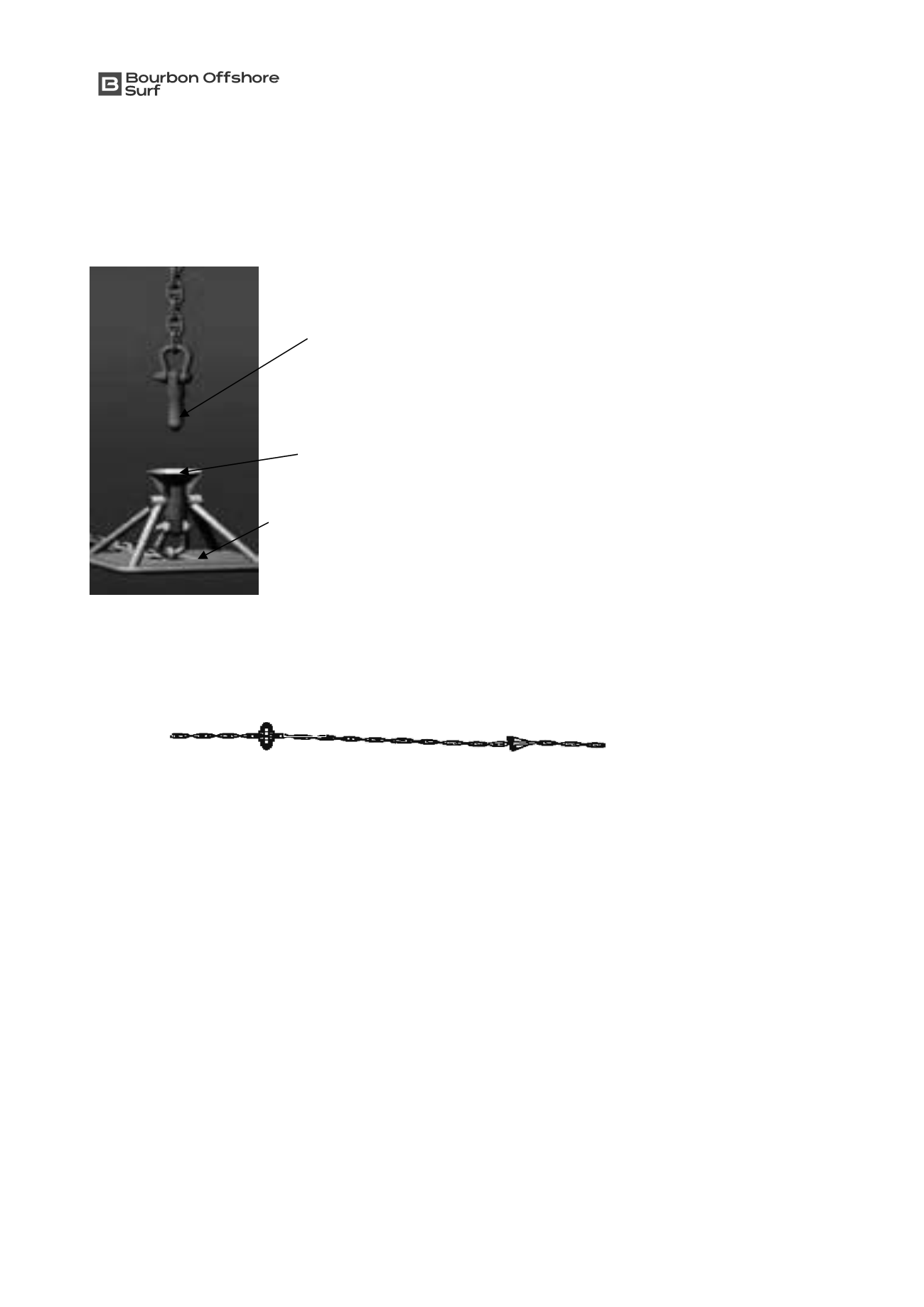
Connector
i
s
composed
of
fema
l
e
(B)
and
ma
l
e
(
C
)
part
ca
ll
ed
“ba
ll
grab
”. F
ema
l
e
connector
i
s
connected
to
the
anchor wh
il
e ma
l
e
connector
i
s
the
end of
the moor
i
ng
li
ne
.
T
op entry
connector
engages w
i
th
no
RO
V
I
ntervent
i
on
,
but
on
l
y
RO
V mon
i
tor
i
ng
.
x
Chaser
trap
:
Chaser
trap
i
s
a
p
i
ece
of
cha
i
n
(20
meters
;
d
i
ameter
3
‘’.
A
stea
l
d
i
sc
(
d
i
ameter
80
cm
) i
s
f
i
tted
on
i
nsert
s
i
de when
a
con
i
ca
l
p
l
ate
i
s mounted on
the
other
end
.
T
he
chaser
trap
perm
i
ts
to
l
oc
k
the
eye
r
i
ng
of
the
retr
i
ev
i
ng
pennant when
recovery
. I
t
runs
a
l
ong
the
li
ne
then
l
oc
k
s
after
con
i
ca
l
p
l
ate
i
n between
the
two dev
i
ces
.
T
o
i
nsert
T
oward p
l
ateform
li
ne
x
Advantages
of
S
EP
L
A Anchor
:
-
More eff
i
c
i
ent
than
S
uct
i
on Embedded Anchors
(S
EAs
).
-
Si
gn
i
f
i
cant
l
y
l
ess
cost
l
y
than
S
EAs
.
-
S
ystem
des
i
gned
to be
recoverab
l
e
.
-
N
oth
i
ng mechan
i
ca
l l
eft
subsea
(i
e
va
l
ves
).
-
Mu
l
t
i
p
l
e
S
EP
L
As m
i
ght be
carr
i
ed on an
i
nsta
ll
at
i
on
vesse
l
due
to
the
i
r
sma
ll
er
s
i
ze
.
-
D
es
i
red
geograph
i
ca
l
pos
i
t
i
on and depth penetrat
i
on
can be
read
il
y ach
i
eved
.
-
D
es
i
gn
can be e
x
trapo
l
ated
to h
i
gh
capac
i
ty
types
i
n
very deep water
i
n
a pract
i
ca
l
fash
i
on
.
x
S
EP
L
A Anchor
i
nsta
ll
at
i
on:
I
nsta
ll
at
i
on
i
s
carr
i
ed out w
i
th a
spec
i
f
i
c
suct
i
on
anchor
(
fo
ll
ower
);
S
uct
i
on anchor
i
s
a
cy
li
nder w
i
th a
vacuum
system
on
top
. B
ottom
of
the
cy
li
nder
i
s
shaped
to
rece
i
ve
the anchor
p
l
ate
.
I
nsta
ll
at
i
on
i
s
dea
l
t
by
a
spec
i
f
i
c
vesse
l (1)
for
the
suct
i
on
anchor
(B)
on
the
seaf
l
oor
.
Anchor
(
C
) i
s
secured
i
ns
i
de
.
B
y means
of
i
ts we
i
ght
,
the
suct
i
on
anchor
penetrates
the
sea
bottom
,
and
then
vacuum
dev
i
ce w
ill
he
l
p penetrat
i
on
.
W
hen
correct penetrat
i
on
i
s
ach
i
eved
,
the
RO
V ma
k
es
free p
l
ate anchor
from
suct
i
on anchor
(
3
).
S
uct
i
on anchor
can
then
be
removed
.
A
second
vesse
l (2) l
owers
at
the meant
i
me
the mudmat
(
A
).
C
A
B
Vers
i
on
SF(BOS-
P
RD-0
7
01.000
5
-
ver
.
C
R). O
r
i
g
i
na
l D
ate:
3
1/12/201
5
.
Vers
i
on
D
ate:
N/
A
.
Va
li
d
vers
i
on
on
l
y on QM
S
s
i
te
.
Page
43
of
60
Procedure prepared by:
BOS
Head
of
O
perat
i
ons
.
Approved
by:
BOS
Head
of
O
perat
i
ons
.
Va
li
dated by:
BOS
Qua
li
ty
R
epresentat
i
ve
.
619